ESP32 Projects for Beginners: Setup, Wi-Fi, and Sensors
Four ESP32 projects for beginners: set up the Arduino IDE, blink an LED, connect to Wi-Fi, read a DHT22 sensor, and run a web server, plus the pins to avoid.
The ESP32 is a microcontroller with Wi-Fi and Bluetooth built in, two cores, and a price around three to eight dollars depending on the board. That combination is why it displaced the Arduino Uno for anything that needs to talk to a network, which is most things worth building.
Two references are worth bookmarking before you start, because most beginner problems are answered in one of them: the Arduino-ESP32 documentation from Espressif for the core itself, and the GPIO reference for which pins are safe to use, which is the single most common cause of a board that will not boot.
This is the path I would put a beginner on: get the toolchain working, blink an LED to prove it, connect to Wi-Fi, read a sensor, serve a page. Each step is small and each one rules out a category of problem, which matters because the failures here are mostly silent.
Which ESP32 board should you buy?
"ESP32" is a family, not a part. The differences matter more than the listings suggest.
| Chip | Notes | Good for |
|---|---|---|
| ESP32 (original) | Dual core, classic Bluetooth plus BLE, the most tutorials and library support | Your first board. Buy this one |
| ESP32-S3 | Dual core, native USB, extra RAM, hardware acceleration for display work | Screens, LVGL interfaces, camera projects |
| ESP32-C3 | Single core RISC-V, cheaper, lower power, BLE only | Small battery sensors where cost matters |
| ESP8266 | The older predecessor. Still sold, fewer pins, no Bluetooth | Nothing new. Skip it |
Get a DevKit board with a USB port and pin headers already soldered, not a bare module. Around thirty pins broken out, a USB-C connector, and an onboard LED. That is the standard "ESP32 DevKit V1" shape and it is what nearly every tutorial assumes.
Setting up the Arduino IDE
The ESP32 does not appear in the Arduino IDE by default. You add it through the board manager.
In File, then Preferences, add this to Additional Board Manager URLs:
https://espressif.github.io/arduino-esp32/package_esp32_index.jsonThen in Tools, Board, Boards Manager, search for "esp32" and install the Espressif Systems package. Select "ESP32 Dev Module" as your board, then pick the port your board is on.
Project 1: blink, and why it is worth doing
It proves the toolchain, the cable, the driver and the upload process all work. When something breaks later you want to already know this part is sound.
// The onboard LED is GPIO 2 on most ESP32 DevKit boards.
#define LED_PIN 2

void setup() {
  Serial.begin(115200);
  pinMode(LED_PIN, OUTPUT);
}

void loop() {
  digitalWrite(LED_PIN, HIGH);
  Serial.println("on");
  delay(1000);
  digitalWrite(LED_PIN, LOW);
  Serial.println("off");
  delay(1000);
}
Open the Serial Monitor and set it to 115200 baud. If you see garbled characters, the baud rate in the monitor does not match Serial.begin(). That is the single most common "my board is broken" report and it is a dropdown.
Some boards need you to hold the BOOT button while the IDE prints Connecting........ and release it once uploading starts. Boards with automatic reset circuitry do not, but if uploads fail with a timeout, try it before concluding anything else.
Project 2: connecting to Wi-Fi
This is the whole reason to choose an ESP32, and it is about ten lines.
#include <WiFi.h>

const char* ssid = "your-network";
const char* password = "your-password";

void setup() {
  Serial.begin(115200);
  delay(100);

  WiFi.mode(WIFI_STA);
  WiFi.begin(ssid, password);

  Serial.print("Connecting");
  while (WiFi.status() != WL_CONNECTED) {
    delay(500);
    Serial.print(".");
  }

  Serial.println();
  Serial.print("Connected. IP address: ");
  Serial.println(WiFi.localIP());
}

void loop() {}
Three things catch people here, and none of them produce a useful error.
The ESP32 is 2.4GHz only. It cannot see a 5GHz network at all. If your router presents both bands under one name, the board may connect unreliably or not at all. Give the 2.4GHz band its own SSID while you are testing.
That while loop is infinite. A wrong password prints dots forever with no indication that the password is the problem. In anything real, count the attempts and do something else after twenty seconds.
WPA3-only networks will not work on older ESP32 core versions. Set the router to WPA2 or mixed mode.
Project 3: reading an ESP32 DHT22 sensor
A DHT22 measures temperature and humidity, costs a few dollars, and needs three wires. It is the standard first sensor.
#include <DHT.h>

#define DHT_PIN 4
#define DHT_TYPE DHT22

DHT dht(DHT_PIN, DHT_TYPE);

void setup() {
  Serial.begin(115200);
  dht.begin();
}

void loop() {
  // The DHT22 cannot be read faster than every 2 seconds.
  delay(2000);

  float humidity = dht.readHumidity();
  float tempC = dht.readTemperature();

  // Failed reads return NaN rather than throwing. Check every time.
  if (isnan(humidity) || isnan(tempC)) {
    Serial.println("DHT read failed");
    return;
  }

  Serial.printf("%.1f C  %.1f %%\n", tempC, humidity);
}
Wiring: VCC to 3V3, GND to GND, DATA to GPIO 4. Most DHT22 breakout boards include the pull-up resistor on the data line. A bare sensor does not, and needs a 10k resistor between DATA and VCC or every read returns NaN.
That isnan check is not defensive padding. The DHT22 fails a read now and then under completely normal conditions, and without the check you get nan propagating into whatever you do next.
Which pins will waste an afternoon?
Not all GPIOs are usable, and the ones that are not fail in confusing ways rather than obviously.
| Pins | Problem |
|---|---|
| 6 to 11 | Wired to the internal flash chip. Using them crashes the board |
| 34, 35, 36, 39 | Input only. No output, and no internal pull-up resistors |
| 0, 2, 12, 15 | Strapping pins, read at boot. A sensor pulling them the wrong way stops the board booting |
| ADC2 pins (0, 2, 4, 12-15, 25-27) | Analog reads on these fail whenever Wi-Fi is active. Use ADC1 pins (32-39) for analog sensors |
That last row is the one I lost the most time to. An analog sensor works perfectly, you add Wi-Fi, and the readings become garbage with nothing to connect the two events. Use GPIO 32 to 39 for anything analog and the problem never occurs.
Safe general-purpose pins: 4, 5, 13, 14, 16, 17, 18, 19, 21, 22, 23, 25, 26, 27, 32, 33. Start there.
Project 4: an ESP32 web server
This is the point where it stops feeling like a microcontroller exercise. The ESP32 serves a page on your network showing its own sensor readings.
#include <WiFi.h>
#include <WebServer.h>
#include <DHT.h>
#define DHT_PIN 4
DHT dht(DHT_PIN, DHT22);
WebServer server(80);
void handleRoot() {
float t = dht.readTemperature();
float h = dht.readHumidity();
String html = "<!doctype html><html><head>";
html += "<meta name='viewport' content='width=device-width,initial-scale=1'>";
html += "<meta http-equiv='refresh' content='10'>";
html += "</head><body style='font-family:system-ui;text-align:center'>";
html += "<h1>" + String(t, 1) + " °C</h1>";
html += "<p>" + String(h, 1) + "% humidity</p>";
html += "</body></html>";
server.send(200, "text/html", html);
}
void setup() {
Serial.begin(115200);
dht.begin();
WiFi.begin("your-network", "your-password");
while (WiFi.status() != WL_CONNECTED) delay(500);
Serial.println(WiFi.localIP());
server.on("/", handleRoot);
server.begin();
}
void loop() {
server.handleClient();
}Open the IP address the board printed and you have a sensor readout on your phone. The viewport meta tag is there because without it the page renders at desktop width on a phone and the text is unreadable, which is the same reason it belongs on any page, and the starting point for responsive design with Tailwind CSS. The refresh tag is a crude way to update; a real interface would fetch JSON, and at that point you are building fetching data in React that happens to talk to a microcontroller.
Replacing delay with millis
delay() blocks everything. It is fine in a blink sketch and wrong in almost anything else. The alternative is to check whether enough time has passed and keep going otherwise.
unsigned long lastRead = 0;
const unsigned long READ_INTERVAL = 5000;

void loop() {
  server.handleClient(); // runs thousands of times a second

  unsigned long now = millis();
  if (now - lastRead >= READ_INTERVAL) {
    lastRead = now;
    readSensor();
  }
}
Subtracting the way round shown above matters. millis() overflows back to zero after about 49 days, and now - lastRead with unsigned arithmetic still gives the correct interval across that rollover. Writing it as now > lastRead + INTERVAL looks equivalent and breaks once, seven weeks in, in a way nobody will ever reproduce deliberately.
Where to take these ESP32 projects next
Once these four work, the interesting projects are combinations of them. Publishing readings over MQTT so several boards feed one dashboard. Running on a battery, which means deep sleep and a completely different program structure. Driving a display with LVGL. Controlling a relay for home automation, at which point you should read carefully about mains wiring before you touch it.
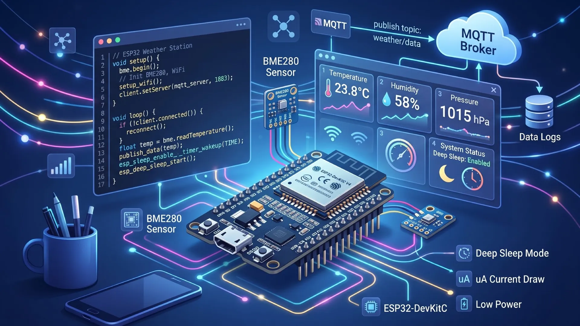
The natural next build is a full ESP32 weather station, which takes the sensor and Wi-Fi pieces here and adds deep sleep, battery power and MQTT so it can run outdoors for months on a charge.
Frequently asked questions
Which ESP32 board should a beginner buy?
The original ESP32 on a DevKit V1 style board with pin headers already soldered, a USB connector and an onboard LED. It is dual core, has both classic Bluetooth and BLE, and has by far the most tutorials and library support, which matters more than specifications when you are stuck at midnight and need an answer that matches your board. The S3 is better for displays and cameras and has native USB. The C3 is cheaper and single core, which suits small battery sensors. The older ESP8266 is not worth starting on now that ESP32 boards cost about the same. Buy two rather than one: having a known-good board to swap in is the fastest way to tell a code problem from a hardware problem, and it costs a few dollars against an evening of doubt.
Why is no serial port showing for my ESP32?
Usually a missing USB-to-serial driver. Most boards use a CP2102 or a CH340 chip, and each needs its own driver on Windows and macOS, though Linux generally has both in the kernel already. The other common cause is a charge-only USB cable, which powers the board so the LED lights up and everything looks alive, but carries no data lines at all. Both failures look identical from the outside, so try a different cable before installing anything, because it is the faster test and the more likely culprit if the cable came with a phone. If the port appears and uploads still fail, hold the BOOT button while the upload starts, since some boards lack the auto-reset circuit that puts the chip into bootloader mode on its own. Checking device manager or the tty listing before and after plugging the board in tells you within seconds which half of this you are dealing with.
Why will my ESP32 not connect to Wi-Fi?
The ESP32 is 2.4GHz only and cannot see a 5GHz network at all, so a router presenting both bands under a single name is the usual cause: the phone you tested with joins the 5GHz band and the board simply never finds the network. Give the 2.4GHz band its own SSID while testing, even temporarily. WPA3-only networks also fail on older ESP32 core versions, so set the router to WPA2 or mixed mode. After that, check the obvious things properly: SSIDs and passwords are case sensitive, hidden networks need extra configuration, and a captive portal will never work. Print the status code from the Wi-Fi library rather than looping on connected, because it distinguishes a wrong password from a network that was never found, and those have different fixes. Signal strength is worth printing too, since a board that connects on the bench and fails in the garden is a range problem rather than a code one.
Which ESP32 GPIO pins should I avoid?
Pins 6 to 11 are wired to the internal flash and using them crashes the board immediately. Pins 34, 35, 36 and 39 are input only, so they cannot drive an LED or a relay no matter how the code reads. Pins 0, 2, 12 and 15 are strapping pins sampled at boot, so a sensor pulling one the wrong way stops the board booting at all, which presents as a dead board rather than as a wiring mistake. And ADC2 pins stop working for analog reads whenever Wi-Fi is active, which is a genuinely confusing failure because the same code works fine until you add networking. Use pins 32 to 39 for anything analog. Pinouts differ between board variants, so check the diagram for the exact board you bought rather than a generic one.
Related Articles